XMT-R Controls and Connectors
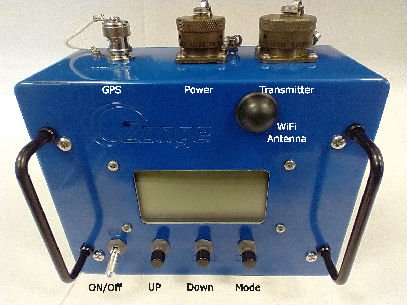
Control elements and connectors of the XMT-R.
The XMT-R user interface is based on 128 x 64 pixel transflective display and three push buttons, UP, DOWN and MODE, for menu control. The transflective display makes it easy to read even in bright sunlight. An LED backlight allows operations at night.
On the back there are a 50 Ohm BNC connector for an active GPS antenna, a power connector and the Zonge transmitter connector.
ZONGE Transmitter Connector Pinout
The transmitter connector on the XMT-R is a 15 pin circular MIL spec connector type MS3112E14-15P the mating connector on the cable is a MS3116F14-15S.
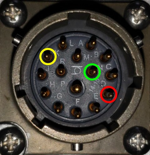
Pinout of the 15 pin MIL transmitter controller connector. POL is on pin D (red), COMMON (GND) is on pin N (green) and ON/OFF is on pin K (yellow).
Use a ZONGE cable type XMT/16-CN/6 to connect the XMT-R to a ZONGE transmitter.
ZONGE Power Connector
The power connector on the XMT-R is a 3-pin MIL spec circular connector of type KPT02E12-3S.
The positive lead of a stable 9 - 16 V DC source must be connected to pin A.
The negative lead must be connected to pin B.
Pin C is not connected.
GPS Antenna Connector
The GPS antenna is connected with a 50 Ohm BNC connector. Connect an 3.3 V active GPS antenna with a minimum gain of 15 dB and a maximum gain of 30 dB to the antenna connector.